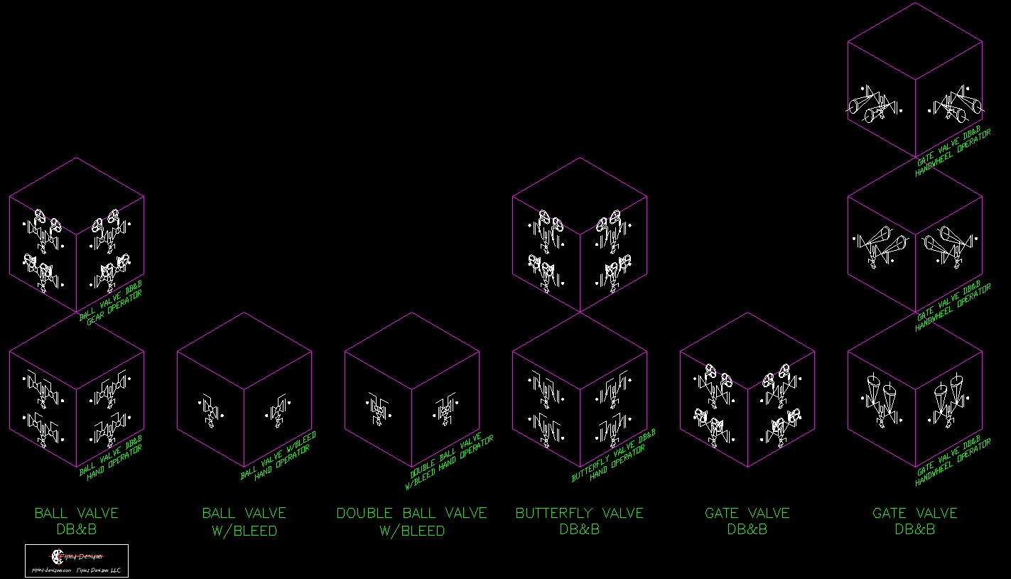
Below are some ways that will help you in reading them: The comprehensive engineering procedures are described using a P&ID.

Piping and instrumentation diagram example P&ID Sample Iso standard for P&ID symbols instruments and identifying letter codes are needed to read P&IDs. This code and symbol can help us identify the device, its location, and its role in the process. P&ID symbols and codes indicate each process instrument. Piping, mechanical, civil, electrical, and instrumentation engineers use them extensively. P&IDs build, manage, and repair chemical processing plants.

The process flow schematic doesn’t depict a plumbing facility or pressure-flow instruments. PFD shows process engineers how chemical fluids travel through a chemical process’s major equipment. These diagrams are popular in engineering. Pipes and other aspects of a physical process flow are shown. According to wiki, A piping and instrumentation diagram shows a processing plan’s piping, process equipment, instrumentation, and controls.

The process flow diagram (PFD), which explains a relatively typical flow of plant processes about significant equipment of a plant facility, and the piping and instrumentation diagram have a close relationship. Image Source: Valve symbols in process and instrumentation diagrams What is P&ID? dust proof forged steel trunnion ball valve.


 0 kommentar(er)
